Signal generator generally refers to a circuit or instrument that can automatically generate sine wave, square wave, and triangle wave voltage waveforms. The circuit form can be composed of op amps and separate components; it can also use a monolithic integrated function generator. Here, a discrete component is used to design a signal generator that can generate three common experimental waveforms, and the parameters of each component are determined. Through adjustment and analog output, the circuit can generate three signal outputs with a frequency of less than 10 Hz. The advantages of simple, clear structure and low cost. This circuit has been used for experimental operation of actual circuits.
1 Waveform conversion principle
1.1 Generation of square wave and triangle wave
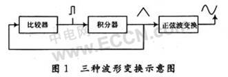
The square wave-triangle wave-sine wave signal generator circuit is composed of an operational amplifier circuit and discrete components, and its structure is shown in FIG. 1. It uses a comparator to generate a square wave output; the square wave generates a triangular wave output through integration.
1.2 The use of differential amplifier circuit to achieve the transformation of triangle wave-sine wave
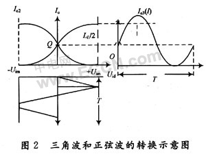
The principle of waveform transformation is to use the nonlinearity of the transmission characteristic curve of the differential amplifier. The waveform transformation process is shown in Figure 2. It can be seen from Figure 2 that the more symmetrical the transmission characteristic curve, the narrower the linear region is; the triangle wave amplitude Uim should just make the crystal close to the saturation region or the cut-off region.
2 Circuit design and parameter adjustment
According to the design function, the circuit design process is divided into three parts: sine wave, square wave and triangle wave.
2.1 Generation and conversion circuit of square wave and triangle wave
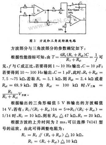
U1 in Figure 3 constitutes a non-inverting input hysteresis comparator circuit for generating an output square wave. The operational amplifier U2, the resistor Rp2 and the capacitor form an integrating circuit, which is used to take the square wave output from the U1 circuit as an input and generate an output triangular wave.
2.2 Sine wave generating circuit
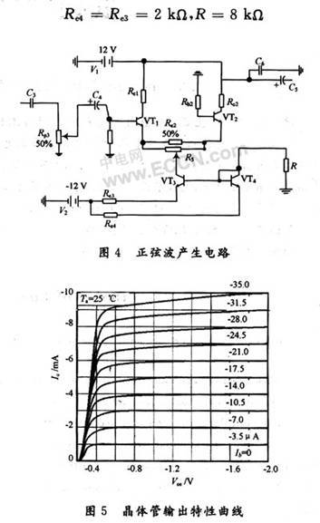
The sine wave generating circuit is shown in Figure 4. Since the differential amplifier circuit is selected to transform the triangle wave to a sine wave, the KSP2222A type tube is selected, and its static curve image is shown in FIG. 5.
According to the static characteristic curve of KSP2222A, the center static current and voltage of the static working area are selected as follows:
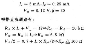
Because the static operating point has been determined, the static current becomes known. The size of each resistance in the mirror current source can be calculated according to the KVL equation:
2.3 System Integration
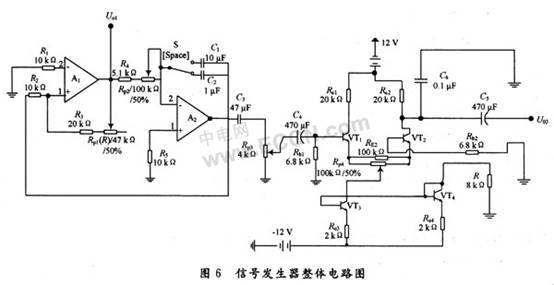
After the sub-circuits are concentrated on a circuit board and the power and ground terminals are shared, the structure of the entire signal generator becomes compact and beautiful. The integrated circuit diagram is shown in Figure 6.
3 Simulation experiment results and analysis
3.1 Simulation results
Use Multisim software to draw the circuit diagram, connect the oscilloscope at the corresponding point, and simulate the circuit result.
Changing the value of Rp2, the output result from 2.4 kΩ to 5.6 kΩ is compared as follows.
3.2 Results analysis
(1) Frequency range
To facilitate measurement, connect the square wave signal on the circuit diagram to the oscilloscope, close the switch with C1 = 10μF, disconnect the switch with C2 = 1μF, then adjust Rp2, and measure the variation range of the square wave signal frequency at this time Turn on the switch of C1, close the switch of C2, adjust Rp2 in the same way, and record the variation range of the frequency of the square wave signal. The results are shown in Table 1.
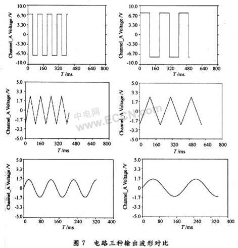
The comparison of the three output waveforms of the circuit is shown in Figure 7.

(2) Output voltage
Connect the square wave signal to the oscilloscope and adjust Rp1 to get the square wave peak-to-peak Vpp = 14 V; remove the square wave signal and connect to the triangle wave signal, adjust Rp1 to measure the triangle wave peak-to-peak Upp = 5 V; connect the sine wave signal to the oscilloscope, Adjust Rp3 and Rp4, measured sine wave peak-to-peak Upp = 2.8 V.
The performance index of the function signal generator mainly depends on the selection of components and the selection of circuit component parameters. Connecting an oscilloscope to the circuit will have a certain impact on the circuit's load matching, which in turn affects the waveform output. In this design, Multisim software is used to simulate the designed circuit, and the results are simulated. The circuit can generate three signal waveforms below 10 Hz, and the output voltage can reach a reasonable range. The circuit has been used in experimental operations.
Latex Dog Toys Safe,Latex Dog Ball,Latex Toys For Small Dogs,Funny Interactive Dog Christmas Toys
NINGBO BRIGHT MAX CO., LTD. , https://www.smartrider-horsecare.com