introduction
The contact card in the IC smart card and the non-contact IC smart RF card are highly secure and confidential. Make it stand out in the field of IC cards. Especially in the field of public transport industry electronic ticket, medical insurance in health and medicine, parking lot and other closed venue management, identification, electronic patrol security system in intelligent buildings, etc., the application prospects are particularly broad [1].
At present, the mainstream technology in the international non-contact IC smart RF card is PHILIPS' MIFARE technology. Has been formulated as an international standard - IS014443 TYPEA standard. This module uses the domestic non-contact card reader chip FM1702, which is based on this international standard. The module is small in size and easy to embed into the application system.
1 Introduction to FM1702SL
FM1702SL is a special chip for contactless card reader designed by Fudan Microelectronics Co., Ltd. based on IS014443 standard. The chip is manufactured by 0.6 micron CMOS EEPROM process. Encryption algorithms that support the ISOl4443 typeA protocol and the MIFARE standard. An analog modem circuit is integrated inside the chip. Therefore, it is only necessary to overlap the minimum number of peripheral circuits to work. The FM1702SL chip supports the SPI interface, and its digital circuit has two voltage working modes, TTL and CMOS. It is especially suitable for the application of card readers for billing systems such as water, electricity and gas meters under the ISO14443 standard. The chip's three power supplies are suitable for low voltages.
2 Non-contact reading and writing system
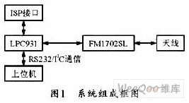
The system is mainly composed of MCU, FM1702SL, RS232/I2C communication module, ISP online debugging interface and antenna. The block diagram of the system is shown in Figure 1. The user can simply operate the card by sending a command through the selected UART or IIC interface. The MCU controls the FM1702SL according to the received command, and the FM1702SL drives the antenna to read and write the MiFare card.

The system MCU adopts PHILIPS enhanced single-chip microcomputer LPC931, which can be debugged online by ISP and runs stably. The RF contactless IC card reader module supports both IIC and UART communication interfaces. By setting the level of the module's pins, you can determine whether the module's communication port is IIC or UART.
3 antenna design [2]
System data is stored in passive Mifare cards. The main task of the read/write module is to transfer energy to the Mifare card. And establish communication with it. The antenna is an important part of the non-contact IC card reading and writing module. During the communication between the reader module and the non-contact IC card, the antenna is used to generate magnetic flux capable of transmitting and receiving RF signals. Magnetic flux is used to power the card and transfer information between the reader module and the card. Therefore, the current of the antenna coil is required to be the largest in the design for generating the maximum magnetic flux and to ensure sufficient bandwidth. The performance of the read/write module is directly related to the parameters of the antenna. After optimizing the performance of the antenna. The read/write module can read up to 10 cm.
Since the frequency of the FM1702SL is 13.56 MHz. It is a short band, so a small loop antenna can be used. The small loop antenna has a square shape, a circular shape, an elliptical shape, a triangular shape, etc., and the system uses a rectangular antenna. There is no strict limit between the maximum geometry of the antenna and the operating wavelength. Generally defined as:
L/λ≤1/(2π) (1)
Where L is the largest dimension of the antenna and λ is the operating wavelength. For a 13.6 MHz system, the maximum size of the antenna is around 50 cm.
In the antenna design, the quality factor Q is a very important parameter. For the reader antenna of an inductively coupled RFID system. A higher quality factor value will also result in a higher current intensity in the antenna coil, thereby improving the transmission power to the card. The formula for calculating the quality factor is:

Where f0 is the operating frequency, Lcoil is the size of the antenna, and Rcoil is the radius of the antenna.
The bandwidth of the antenna can be easily calculated by the quality factor:
B=f0/Q (3)
It can be seen from the equation that the transmission bandwidth of the antenna is inversely proportional to the quality factor. therefore. An excessively high quality factor results in a reduction in bandwidth, which reduces the modulation sideband of the reader and prevents communication with the card. The best quality factor for a typical system is 10-30 and the maximum cannot exceed 60.
4 hardware circuit
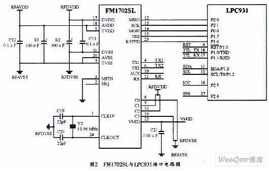
Figure 2 shows the interface circuit between the FM1702SL and the main part of the MCU. The system works by receiving the data of the host computer and according to the received related commands. Also. It can also be set to the automatic card finding mode, without the host computer frequently sending the card search instruction, that is, when the card enters the antenna area, a low level is displayed on the ICC pin to inform the upper computer, and the upper computer directly reads through the card search instruction. Take the card serial number.

5 software design [3]
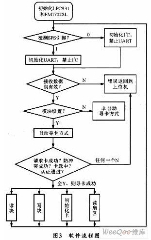
The reader software programming uses a standard C language program to implement a series of operations on the contactless IC card. Mainly: LPC931 microcontroller initialization, FM1702SL initialization, receiving command data processing, IC card reading and writing, anti-collision, password verification and card block (data block) operating procedures.
The process of reading and writing the card is a more complicated program execution process. The software flow chart is shown in Figure 3. The process of reading and writing the card needs to execute a series of operation instructions and call multiple C51 functions. If the automatic card finding mode is adopted, the MCU needs to automatically search for the card every 0.5 seconds. If the card is found, the ICC is set to 1.

5.1 Request operation
When a Mifare card is within the working range of the read/write module antenna. The host computer controls the read/write module to issue a REQUEST all (or REQUEST std) command to the card by sending a command. The card's ATR will be activated and the card type (TagType) number (2 bytes total) in the card BlockO will be transferred to the read/write module. The first step of establishing a card is to communicate with the module. If the request card operation is unsuccessful, the other operations of the card module will not proceed.
5.2 Anti-collision operation
If more than one Mifare card is within the working range of the card reader module antenna, the read/write module will first communicate with each card. To get the serial number of each card. Since each Mifare card has its own unique serial number, the read/write module can guarantee that only one card can be operated at a time according to the serial number of the card. The return value of the card obtained by this operation is the serial number of the card.
5.3 Card selection operation
After completing the above two steps, the card reading module must perform a selection operation on the card. After performing the operation, return the card serial number (UID) on the card.
5.4 Certification operation
After the above three steps, when confirming that a card has been selected. The card reading and writing module is before the card is read or written. The password already set on the card must be authenticated, and if it matches, further read and write operations are allowed.
5.5 read and write operations
The final operation of the card includes card initialization card value, card reading, card writing, value addition, depreciation, storage, and the like.
6 Conclusion
This paper mainly introduces a design method of radio frequency identification read/write module based on FM1702SL. This module only needs the host computer to send commands through the selected UART or IIC interface to complete the operation of the card. The practical application proves that the read/write module has good performances such as stable circuit, easy embedding into other modules, and low power consumption. Can be easily applied to a variety of different RFID applications. Such as attendance system, access control system, bus toll system. And a variety of water, electricity, gas meter billing systems, etc., has a very broad application prospects.
Pastry And Vegetable Processing Machines
With an experience of over 30 years, Helper has designed and manufactured full series of pasta and vegetable processing machines, like bakery industrial dough mixer, automatic fresh and cooked noodle production line, vegetable cutting machine, slicer and dicer, automatic dumpling machine/dumpling machines, sesame mill, pancake forming machine etc. A pasta branch company was estblished with the development the business, owning a group of talented technical people, skilled production workers, and a professional sales and after sales service team. Many famous companies such as Dali Group, Panpan Group, Wanchai Ferry, Sinian Group, and so on have chose Helper as their strategic supplier and partner.
Pastry Processing Machines,Food Packaging Machines,Vegetable Processing Machines,Noodle Production Line,Dumpling Machines
Helper Machinery Group Co., Ltd. , https://www.helperfoodtek.com