Commissioning of FN-250 steel drum automatic seam welding machine (2)
Tan Xinhua, 3602 Factory of the Chinese People's Liberation Army
Chapter III Adjustment of the "Z" Shape Orbit
Before the seam welding of the 200 liter steel drum, the steel plate of the barrel body needs to be rounded to form a barrel body having a predetermined radius of curvature and a certain lap width, thereby preparing for the subsequent seam welding process. The mechanism of the manual semi-automatic welding machine and the automatic welding machine forming the barrel body has obvious differences. The following begins with the mechanism of forming a lap joint between a semi-automatic welder and an automatic welder, and then introduces the "Z" track structure of the FN-250 automatic welder, and finally introduces the FN-250 welder. Z" track adjustment method.
First, the manual semi-automatic seam welding machine and the automatic seam welding machine form a lap joint mechanism.
(1) Forming mechanism of manual semi-automatic seam welding machine
Before the seam welding of the semi-automatic welding machine, the barrel body is rounded and needs to be spot-welded by the spot welding machine to form the specified radius of curvature and the edge size. The manual spot welding process and schematic are as follows:

Figure 1 Schematic diagram of manual spot welding process
1-slide; 2-spot welder lower arm; 3-spot weld lower electrode; 4-bath body plate short side;
5-point welding upper electrode; 6-edge positioning block; 7-bowl edge to positive arm
When hand spot welding, use the manpower to roll the barrel after the round. Pull in between the upper and lower arms of the spot welder. First, the edge is aligned with the front arm, the two short ends of the barrel are aligned, and the two short sides are hung on the positioning block 6 to start spot welding. After the spot welding is completed, the barrel is pulled out of the arm by hand, and it is transferred into the seam welding process along the slide.
The size of the lap joint of the hand-stitched barrel is determined by spot welding. A cross-sectional view of a commonly used lapped positioning block is shown in Fig. 2.
From the analysis of the latter, we can know that the spot welding machine uses spot welding to determine the prototype of the "Z" track used in the automatic welding machine.
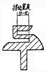
Figure 2 Cross-sectional positioning block
(2) Edge-engaging mechanism of automatic seam welding machine
The schematic diagram of the formation of the seam of the automatic seam welding machine is shown in Figure 3. The upper part of Fig. 3 is a top view of the two short side movement tracks of the barrel body, and the lower part is a sectional view of the corresponding section.
The forming process of the lap joint can be described as follows: under the chain driving, the barrel body after the rounding is sequentially passed through the winding round section and the transition section, and the lap forming section and the welding wheel complete the welding of the barrel weld seam. The lap forming section is the "Z" track of the automatic seam welder.
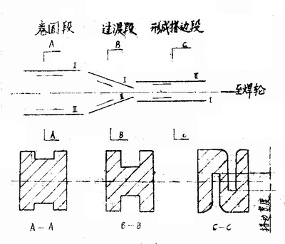
Figure 3 Schematic diagram of the automatic seam welding machine barrel body edge formation
Comparing the formation process of the semi-automatic seam welder and the automatic seam welder barrel body edge, we can see that there are the following differences between the two:
1. The semi-automatic seam welding machine needs spot welding to form the edge, and the automatic seam welding machine does not need spot welding positioning. After the lap joint is formed, the seam welder is started to maintain the formed lap by the bending force of the barrel itself and the mechanical restraint condition.
2. When the barrel body forms a lap, there is a difference in the direction of movement. After the barrel body is spot-welded, the semi-automatic seam welding machine needs to manually pull the barrel body from the feeding direction and pass it to the next process. After the automatic welding machine is formed, the barrel body continues to move forward along the original movement direction. Feed the welding wheel directly to complete the seam welding process.
3. The source of force is different during the formation of the edge. When manual spot welding, the feeding and pulling of the barrel body, alignment and holding, etc., all need to be completed by manpower. In the process of forming the edge, the required manpower is applied by the corresponding mechanism, thus eliminating the worker. Heavy physical labor.
4. On semi-automatic welding machines, the barrel body needs spot welding positioning. In the subsequent seam welding process, the solder joints are prone to burn through, and the defects such as sintering are mostly "Z" rail automatic seam welders. Since spot welding positioning is not required, the above defects are avoided. Thereby improving the quality of the weld.
In the formation process of the barrel body edge, the above-mentioned differences between the automatic seam welding machine and the semi-automatic seam welding machine embodies the superiority of the automatic welding machine and is one of the main principles of the automatic welding machine automatic working.
Second, the "Z" track of the FN-250 welder
According to the distance from the welding wheel, the "Z" track of the FN-250 welder can be divided into the front section (the welding nose part), the middle section (the "Z" rod part), and the rear section. The main view of the "Z" track is shown in Figure 4. The specific structures of the front, middle and rear sections are shown in Figure 5, Figure 6, and Figure 7.
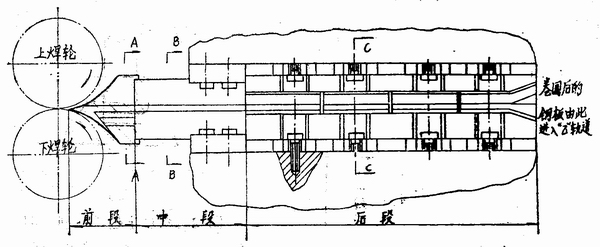
Figure 4 "Z" track main view
The "Z" rail of the FN--250 welder is fixed between the upper and lower welding arms of the main circuit of the welder. The upper and lower welding arms act as a fixed support for it. The "Z" track and the welding arm are electrically insulated by a phenolic glass cloth board. After the barrel body enters the welding, after the machine is wound, the circular section and the transition section shown in Figure 3 enter the "Z" track, and then pass through the rear section, the middle section, the front section of the "Z" track, and then the waist roller. Under the restraint, enter the welding wheel to complete the seam welding process. A cross-sectional view of the rear section of the "Z" track is shown in FIG.
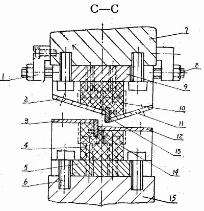
Figure 5 is a cross-sectional view of the rear section of the "Z" track
1-triangular joint plate; 2-left oblique wear plate; 3-left horizontal wear plate; 4-lower circuit guide seat; 5-connect plate; 6-bolt; 7-upper stand;
8-screw; 9-joint plate; 10-upper circuit rail seat; 11-right oblique wear plate; 12-right horizontal wear plate; 13-vertical wear plate;
14-vertical wear plate; 15-low base
It can be seen from Fig. 5 that the rear part of the "Z" track is divided into upper and lower parts, and there is no direct mechanical connection between the two. The upper and lower circuit rail seats are made of an insulating material (phenolic glass cloth board). They are bolted to the link plate and the upper and lower bases secure the "Z" track by the link plates. The main components of the "Z" track - the wear plate (left and right, left and right horizontal) are made of 1Cr18Ni9Ti material, and the vertical wear plate is made of W18Cr4V material. Because the welding machine works, the vertical wear plate and the short side of the barrel move relative to each other, and there is severe friction. Therefore, the vertical wear plate is made of W18Cr4V with high hardness, high heat hardness and high wear resistance. The choice of left and right oblique wear plates and left and right horizontal wear plate materials should have good diamagnetic resistance in addition to good 礴 wear resistance. If the material is not diamagnetic, the magnetic field generated by the powerful welding current (up to more than 10,000 amps) will adsorb the iron slag on the "Z" track during the operation of the welder, thus affecting the barrel in the "Z" orbit. exercise. Therefore, the left and right oblique horizontal wear plates are made of stainless steel material 1Cr18Ni9Ti which has good anti-magnetic effect and good wear resistance.
The left and right oblique, left and right horizontal wear plates and the vertical wear plates are respectively fixed to the upper and lower circuit rail seats by screws. A section of the middle section of the "Z" track is shown in Figure 6:
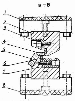
Figure 6 Sectional view of the middle section of the "Z" track
1-Upper insulating bakelite; 2-"Z" bar; 3-upper platen; 4-"Z" bar horizontal wear strip; 5-down slant platen;
6-"Z" rod vertical wear strip; 7-low press plate; 8-under insulating bakelite
As can be seen from Fig. 6, the upper and lower press plates fix the horizontal wear strip and the upper and lower vertical wear strips to the "Z" rod as a whole. The "Z" rod is electrically insulated from the main circuit of the weld by upper and lower insulating bakelite. The wear strip material is W18Cr4V. The pressure plate material is 1Cr18Ni9Ti. A cross-sectional view of the front section of the "Z" track is shown in Figure 7.
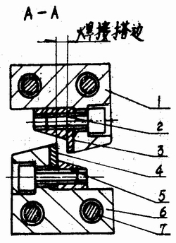
Figure 7 is a cross-sectional view of the front section of the "Z" track
1-Up welding nose; 2-down welding nose plate; 3-up welding nose wear strip; 4-down welding nose wear strip;
5-up welding nose plate; 6-lower nose; 7-welding nose fixing screw
As can be seen from Figure 7, the front section of the "Z" track (also known as the welding nose) is divided into two parts. Secure it to the "Z" rod with bolts. The wear-resistant strip material on the welding nose is W18Cr4V, and the rest is rust steel 1Cr18Ni9Ti.
The above is an introduction to the "Z" track structure of the FN-250 welder. Knowing its structure helps us adjust the "Z" track.
Apartment Furniture,Standard Hotel Furniture,Hotel Suite Furniture,Hotel Furniture Table
PinSheng hotel furniture , https://www.pinshotelfurniture.com